
Baty Vision Systems – Venture 3D CNC
Venture CNC models take the power of fusion software one stage further by completely automating the inspection process. Now advanced features like scanning and best fitting can be done quickly without taking up the time of skilled operators.
CNC programming is a simple teach and repeat process. Just measure the part once and a full CNC program is created automatically. The zoom lens can also be controlled so that magnification changes are all recorded into the program.
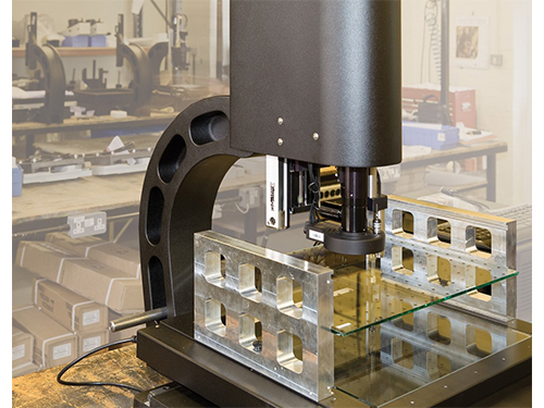
Large Measurement Volume
The use of a touch probe is optimised on a CNC system. Measurements from data points taken using the touch probe can be combined with those taken using video edge detection for optimum speed and reduced inspection times.
A probe changer rack can be installed so that probe modules fitted with a variety of pre-calibrated styli can also be used in the same inspection. When a change of stylus is required, the system automatically puts the current probe module back in the rack and picks up the next to continue the inspection process.

When programming using the touch probe, use only the minimum points required to define each element. Then simply edit in the optimum number of points for each element. The new probe path is then automatically created when the program is played, cutting down both programming and inspection time.
Standard CNC system features include:
- Teach and Repeat programming
- Programmable segmented LED lighting
- 6.5:1 zoom optics (with optional CNC control)
- Optional 12x zoom optics
- High resolution 0.5µm scales for increased accuracy
- CAD import / export
- Scanning & best fitting
- Fully dimensioned part view
- SPC included
- One click output to Excel™
- Autofocus
- 165mm Z axis measuring range on adjustable dovetail slide
- 250mm x 125mm and 300mm x 300mm XY stages available
- Auto program from CAD
Advanced error mapping
Once the X-Z and Y-Z alignment and calibration is completed, every Venture goes through an error mapping process using a calibrated master grid as a reference. Any errors in X, Y, Xdy, Ydx and X-Y squareness are compensated and verified. The grid is then re-positioned in the Z axis and the process repeated to eliminate Xdz and Ydz errors.
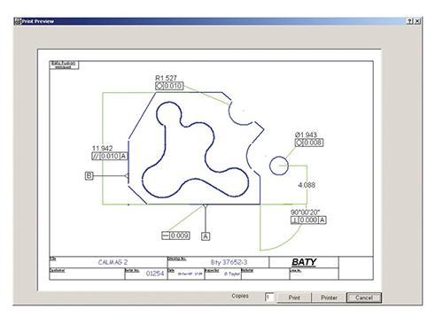
Reporting
Graphical reports show the measured part as a dimensioned drawing with ‘in tolerance’ dims shown in green and ‘out of tolerance’ dims shown in red for an instant pass / fail classification. Geometric call outs can also be shown as well as datum features and true position.
Supplementary tabulated reports show nominals as well as tolerance values with a ‘PASS’ or ‘FAIL’ SPC information can either be reported or exported to excel. Distribution and control charts are also produced.
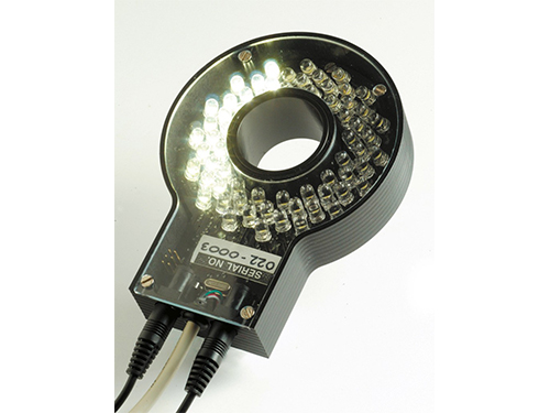
Programmable Segmented Light
Lighting is critical to ensure that the correct edge is measured. Baty’s new programmable LED lighting head allows the user to define any segment pattern to be switched on. This means that oblique lighting conditions can be achieved to illuminate more difficult edges.
Segments can then be rotated and intensity varied to suit the radial position of the edge. Once set, the lighting condition for each measured feature is now automatically programmed and will be reproduced by the software each time a new part is measured. Through the lens (TTL) lighting is included for applications like blind bore measurement. 64 white LED’s are used to ensure Venture’s high quality colour image is achieved.
Only now can this functionality be combined with traditional touch probe technology to offer the ultimate in large format multi-sensing Vision systems – Venture Plus.
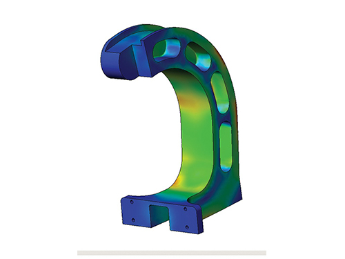
The Venture range of products are designed and built at Baty’s Burgess Hill factory in the south of England. The latest 3D modelling techniques were used to optimise the new base / column design to ensure stability.